Tuesday, February 18, 2025

4 SALE

 The "eGolf" is a fully saleable clean title car, licensed in the state of Illinois as either an EV OR Gas, and insured as a standard VW Golf car.

Reasonable bids will be responded to, the funds spent in this project have created a FUN daily driver and lots of education. 

The funds collected from the sale of this car will go into the next project and will support continued education in our community.

What's left on our list, but don't let this list drive you, we have driven the car for years now and just check things off as we decide to add features.:

  • The car has been driven as is for years now as it has been tweaked slowly with features. It is drivable as is but we would suggest there are additional things you can do to it to make it more refined. 

    • Program internal "ED" computer to automate charging.

      • The Nissan BMS now outputs the individual cell voltages to ED.  ED can communicate with the Brusa charger to turn the charger on and off during the charging cycle to allow for balance time to peak charge.

      • Currently the charger is set to charge to 80% of the pack peak capacity since we could not see individual cell voltages. (We can see them now, so this can be adjusted)

    • Program ED to output CAN data onto the network to cause the VW dashboard to show additional data.  The fuel, RPM, and temp gauges are prime targets. (The MPH gauge is ground driven and therefore works already)

    • Add the power steering or A/C pumps as you wish, we have never found need for either. Mounting points for both are already there.

    • Complete the motion disable charging interlock wiring now that ED can be connected to the charger for peak charging. (It is currently a manual switch in the car)

    • Program the clutch switch (installed) to RPM sync for gear shifts 2nd to 3rd gear.

      • We use 2nd in the city and 3rd on the highway.  We have never needed 1,4,5.

      • Choose to keep using reverse gear, or put in a switch to reverse the motor.  We purposely used reverse gear to prevent a student from slamming forward to reverse by accident.

    • Program ED to turn on the Vicor 400VDC-12VDC inverter automatically.  Currently when switched OFF the battery light on the dash displays just as if the alternator went out.  When switched ON all is happy.

    • Use ED to talk to public chargers.  Currently about half of public chargers will charge it, the other half post an error. We charge in the shop from a standard wall outlet at 220VAC 16Amp in a bit under 4 hours.

    • Program ED to read and automate brake booster pump vacuum tank activation.  Activation is manual now. The car is set for single pedal drive and the brakes are rarely used.

    • Add HV Isolation Monitoring (Pack HV positive and Negative rails are isolated from Chassis but their resistance to Chassis is not currently monitored) It was not a thing to do when we were building the car, it is now on the newest electric cars.

    Special features:

    • Cruise control works with the OEM VW cruise switch.  Tap the button twice or cruise down to change speed by 5mph. Cancel = Coast until Accel pedal is moved again.

    • Heated seats

    • Single pedal drive to and from 0 mph.

    • Tinted “half mast” glass on front windows, rear and back full tint.

    • Standard U.S. SAE J1772 charge port is in OEM gas flap.  Charges in under 4 hours.

    • ED outputs data for observation via wifi to a web browser.  Pages have been set up for a “car” dashboard including [rpm, temperatures of DMOC - stator - core, torque, voltages, amps, kW, regen].  Other pages include i/o states, i/o functions, battery management and cell voltages.

    • Bluetooth module hidden inside stock VW radio to play audio from phone in CD mode

    • Accelerometer triggered Upper Brake Light for Brake Light during Regen


    The eGolf sale comes with a 2001 VW Golf GTI and tow hitch that we have been using as a parts car to support this project, The GTI is drivable, it currently has some heat related electronic shutdown issue though.  Drive 20 minutes in the summer, shutdown, wait an hour for it to cool, starts right back up…

Sunday, December 1, 2024

gumble grumble, HOORAY!

After YEARS of not understanding why the BMS would not read out battery cell voltages and taking EVERYTHING apart twice to look for wiring errors without finding any errors at all, we bought another BMS and plugged it in. The moral of the story is to always open eBay electronics and see if the boards look right before you plug them in. We seem to have gotten TWO bad BMS modules, we plugged the third in and all is happy. IT is GREAT to get it back on the road and out of the workspace. 

Being that it has taken so long to find that one problem, we had moved our focus on to another project. That project has tighter timelines associated to it and takes priority, so with much learning in hand we are looking to permanently move this project out of our space and thus will place it up for sale. Charitable offers welcome, funds will go toward the next project. It has been extremely rewarding working with all the folks and students over the years and seeing their brains light up along with smiles; oh yeah, and the car is really fun to drive! 

The "eGolf" is a fully saleable clean title car, licensed in the state of Illinois as either an EV OR Gas, and insured as a standard VW Golf car. It should go to an owner/group that can finish it up. Now that it is communicating properly several final enhancements can be completed with minimal additional wiring needed to match the programming that could be added to automate charging and other neat things that were in the works. 

The next post will list finishing suggestions.

Saturday, November 9, 2024

Work on the BMS issue

We are still stumped as to why the BMS keeps failing.  After all this work replacing bad modules, we have not found any wiring errors.  Our current path is to investigate this link posting https://mynissanleaf.com/threads/bms-details.17470/

#1Turbo 3
I was fortunate enough to be loaned a BMS board that had been burnt out while trying to converted a Leaf battery pack into a 4 x 100 volt configuration for use in another vehicle.

This is the first time I have looked into a battery controller so some of what I say may be common knowledge. To me it is all new but I though it could be useful to others to know more about the inner working of the battery balancing circuits and how it interfaces with the Leaf.

The board consists of two sections. The first section is common to all ECUs in the Leaf with a CAN interface and RISC processor. This is the part that Leaf Spy communicates with to get battery voltages and shunt settings. The second section is almost totally isolated from the first and consists of 24 custom ASICs that monitor the 96 cell pairs. This is the section I have been looking into in detail.

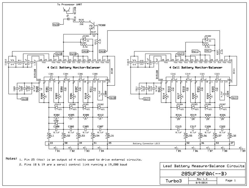
The most interesting part is that the custom ASIC part is coupled to the first section through three photocouplers. Communications with the ASICs is through a serial link starting with a UART pin on the RISC processor and going through the first photocoupler. The output of that photocoupler is looped through the first 12 ASICs then another photocoupler then 12 more ASICs and finally through the last photocoupler back to the RISC processors input UART.

Each ASIC is actually an island onto itself. It gets its power from the four cells it is monitoring and only has a single input signal from its neighbor which with a zener diode is prevent from going negative.

All this isolation is required because the full battery voltage of up to 393 volts is being monitored on a standard circuit board. There is a clear insulating over coating on this section to prevent any leakage that could result in a catastrophic failure of the board.

I am guessing that the zener diodes on the inputs serve two functions. One to dampen any voltage spikes above 6.2 volts. Second to allow the ASIC to function even if one cell is open/shorted. This is important as the command and status must go through all 24 ASICs so they all need to be powered up.

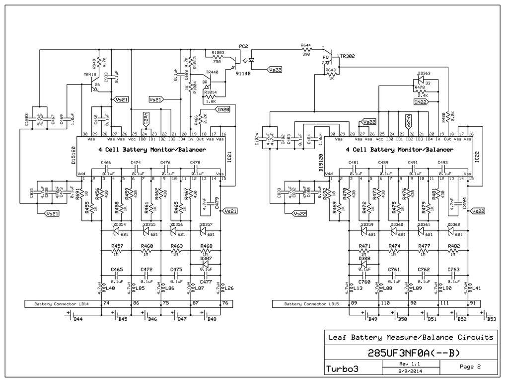
Here is a schematic of the last two ASICs in the chain before the data is shifted back to the processor. Note that the shunt resistor appears to be the 430 ohm 250 mw resistor. So any balancing is going to take a long time at less than a 10 ma load.

Warning: If you are going to try to rewire the BMS to operate with a different battery configuration best to really study this wiring diagram so you understand the voltages your rewiring will put on the ASIC. These are custom chips and as far as I know are only available internally to Nissan or by stripping them off another BMS board.

This shows the last two ASICs in the string before sending data back to the processor through the photocoupler.
BNS5dy.jpg


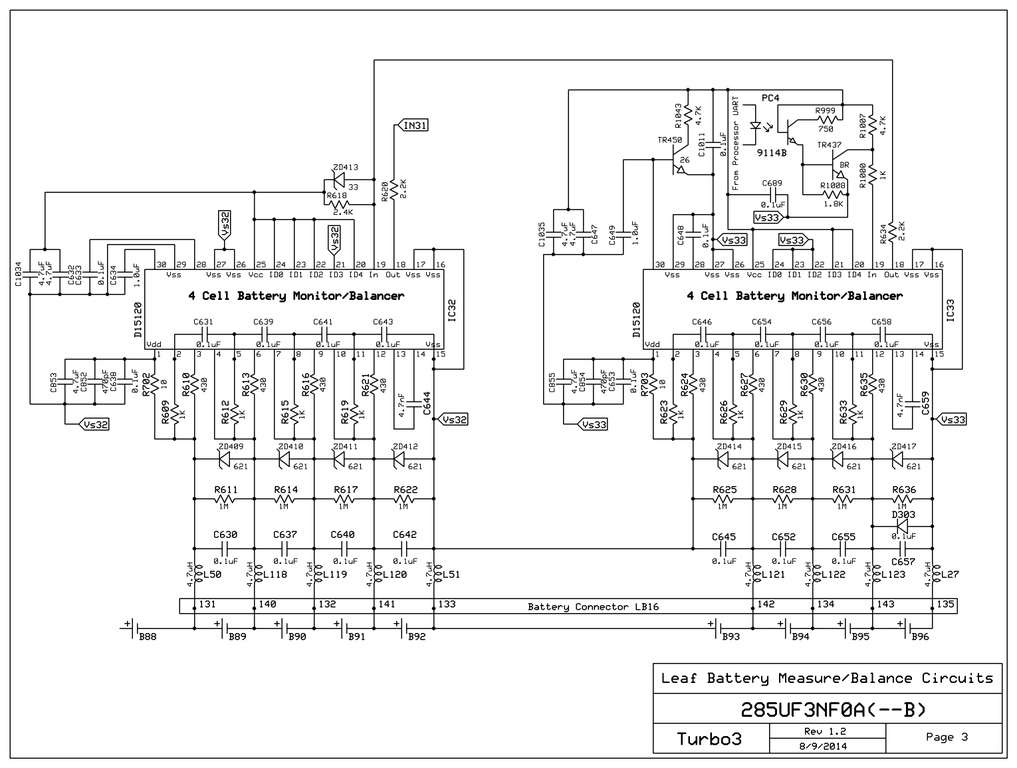
The Service Plug that opens the high voltage circuit requires that the BMS also be split into two isolated sections. This page shows the photocoupler used to isolate the serial control signal between the two groups of 12 ASICs. Note that the negative side of cell 48 is not connected to the positive side of cell 49. If this was not done then when the Service Plug was pulled all the power would try to pass through that connection on the BMS board burning it out in a short order.
TDwVTe.jpg


This shows the first two ASICs in the string with the right one getting commands from the processor through the photocoupler.
Not sure of the purpose of TR450. It seems to allow the ASIC to put a load on the ASIC generated Vcc used to power the photocoupler.
zTtdPQ.jpg
We moved the Service plug from between module 48 and 49 to the positive end of the pack as shown below.  This is page 27 of the 2013 Nissan Leaf 47871 pdf.  Our pack is configured to have 26 modules in the back of the car and two 11 module packs up front.


 Images of our failed boards:


Check back after Thanksgiving break to see what we have figured out.


Sunday, June 23, 2024

Battery pack repair progress

 Since the December removal of the rear battery pack we have:

  • Found 7 replacement modules.  We knew we needed three and found four.  One in New Jersey, one in Pennsylvania, one in Virginia , one in Illinois, and two in California.  Our local dealer would not help us, and neither would the dealer in Chicago.  The dealer in Pennsylvania ordered the modules from New Jersey and Virginia and sent all three to us.  Two of them were bloated and we took them to the unwilling local dealer for disposal.  Apparently dealers are illegally shipping the batteries around the country as "car parts" and not marking them as Lithium batteries because of the extra requirements by carriers.  The local dealer was happy to replace our bad cells.  And we notified the local FedEx facility of the scheme.
  • Four modules in the rear pack were replaced and the pack was repacked.
  • The main connections have all been made and the system started earlier this week.
  • The underbelly skid pans have been reinstalled and the car put back on the ground.
  • Last thing to do is reconnect the BMS which is where we started with all this issue.


Saturday, December 9, 2023

More images of Exothermic event.

 We disassembled the primary failed pack.  It had zero volts on it and showed a short from the leads to the aluminum case.  We unfortunately do not have enough experience in the field to discern any knowledge from the results.  It obviously got hot, vented, smells (lithium), burnt through its case into the module below it.  The module below also shows a short from one terminal to the case, it still has 4 volts on each series of cells therefore 8V across the module.  The module above the failed module shows no damage externally, but is at zero volts.  We are open to suggestions on how we are supposed to dispose of the modules.  


We have lost two BMS in this car and have a third ready to go, but once again, we have checked the wiring against the wiring diagrams and have not yet found a wiring error.  We have checked for shorted BMS wires and resistance in the BMS wiring.  

Wednesday, November 22, 2023

We had an exothermic event.

The pack voltage suddenly dropped and two of the rear pack cells read zero volts.  What is that lithium smell?

Full pack view, find the tip of the blue arrow.This is the rear pack, showing 20 of the 26 modules in the rear pack.


The third and fourth in the stack welded together.


We had an issue while removing the rear pack.  To remove the rear pack from under the car where the gas tank had been you need to disconnect the electrical and BMS leads from the car.  We built the pack with long conduit pigtails such that there are no connectors under the car to leak or get damaged.  We then also place a solenoid in the pack housing to cut off the positive side of the battery from even the pigtail as an added precaution.  We were told that was over kill.  When removing the "dead" negative lead from the front of car connection we noted, "I think my finger is tingling?"  " Can't be, the main fuses are pulled and the positive lead is disconnected." "OK, lets check with a meter."  "The meter says nothing from POS to that connection, must be your finger."  We finished removing the bolt and started to pull the cable from the housing, POW.  Arc from the cable end (Which now needs to be replaced) to the battery case.  "What the %#@^"  

There was 110V from the cable to the chassis of the car.  Is the POS solenoid stuck? No.  BMS wires shorted? No.  Main NEG cable crossed a bolt in the pack? No.  One of the bus bars in the pack came loose? No.  ..... When the battery failed, it internally shorted the entire rear pack to the chassis of the car!  We did not know these batteries could fail this way, Thus it is imperative that a full system fuse be placed as close to the battery output terminals as possible.  We got lucky as the method in which this system failed had no fuse in the failure path, all the fuses were placed up at the front of the car and after the pigtails for ease of accessibility. 

The entirety of the failure was contained in the rear pack housing.  There was much rejoicing.

Thursday, June 16, 2022

Rollin' Rollin' Rollin'

 Since it is running, it spends more time running than being worked on.  Recent work has been:

  • Get the tablet to display the outputs again.  We made a change to the main computer such that it will not look for and read in code from the SD card unless we hold a button down.  This makes the system boot almost instantly and avoids the poor connection issue during cold months preventing the car fro starting.  The caveat is that since the computer is not reading from the card where all the HTML is stored, it would not broadcast the readouts.  Solution was to load the HTML to the tablet directly which turned out to be a challenge in itself but is now complete and working.
  • Working to get the Nissan Leaf Gen II BMS to output the battery voltages on the CAN system.  We have still not successfully completed this step anyone in the area that knows how to get the output is welcome to chime in.  Once we can get the output from the BMS, we can automate the charging process.
  • Crossing 6000 miles on the road.

Wednesday, February 9, 2022

On the road again...

 Over winter break we were able to install the new battery modules, check the wiring, and put is all back together.

To check the wiring we got a couple of boards from Janosch Oppermann.


His board is designed for the 2nd Gen BMS.  After we soldered his board as designed we had not found any wiring errors, so what you see here is after we filled in all the other LED's.  His design reduced risk and checked all the cells in small groups.  As we did not find any errors, we wanted to be sure there was no gross error and made the board messy.

End result is that we found no wiring error in our system.  With no explanation for the fault we checked many other things and came to the conclusion that the BMS chip may have been flawed or we killed it with static before installation.

We do have a blank board to send to the next person that needs one.


The X and ! represent Nissan splits in the pack that do not light.

While the battery was out we took the opportunity to weld in the rear seat pan, seal, sound proof, and paint it.

Next task, back to trying to read the BMS output so we can implement unsupervised charging.

Friday, November 19, 2021

We have spent months finding replacement parts.

Years ago when we started the project we thought we were being smart using stock production car parts in our build such that the junk yards would be full for years with spare parts.  In reality we missed a consideration.  What we did not count on was the solar market buying the junked battery packs from the yards in bulk.  After a couple of months we found a replacement BMS, and after 4+ months we decided to bite the bullet and buy two brand new modules from Nissan.  We tested several modules in our current pack, between 3v-4.2v they take on 56Ah.  Thus our pack is in very good condition.  The used modules for sale online seem to be at a max 70%SOH.  As we understand how the pack would function, the entire pack would drop to the 70%SOH performance level with installation of these modules.  So rather than reduce the performance of the pack significantly from day one we have opted to pay ridiculous funds to Nissan for two new modules.

TAKE TWO.
One of the new modules is already bloated, reject.

OK, now we have two good modules out of the four available in the U.S.  One came from New Jersey, the other from Illinois.  The bad one was from Maryland, our last hope would have been in California...

We hope that over Thanksgiving break we can get the wiring error determined, the packs installed, and maybe the car back rolling!

Saturday, June 26, 2021

One year forward, three years back.

 You may have read in the previous post that the BMS seems to have blown a chip, we still have not figured out what is going wrong, but now we consider ourselves very lucky.  Let this be a WARNING for all of us, plug in your BMS AND check that it is actually working.  We have TWO completely shorted out cells sitting at zero volts.

The bottom two modules of the inner stack read ZERO volts. These represent the center modules 12 and 13 in the leaf pack, they usually have the main disconnect between them.

Thursday, June 10, 2021

We have been working on programming the charging system.

 To date we have been running the Brusa NLG513 charger in manual mode limiting the pack voltage to 388V, sacrificing some range for charging safety.  We recently have been working on the programming to read the individual cell voltages through the Nissan BMS such that we could turn the Brusa charging parameters on/off, amperage up/down as the pack charged.  We have been having one heck of a time getting the data out of the BMS.  And now we know why.


We think this is a 2013 BMS, but the wiring from a 2012 is every so slightly different.  If anyone has a table from Nissan to confirm which diagram we should be following?  If anyone has a new/used version of this same BMS to share with the project?

Summer 2021 update

We made it through the winter.  

Since the car is kept inside, the heated seats were plenty to make it winter driveable as we did not need to scrape the windows.

Cruise control is up and functional on the original VW cruise stalk.  Works just like the original car but better.  Set and Cancel as expected, brake tap cancel as expected, + now gives 5mph increase like new VW models.  Tap the accel pedal to cancel and engage regen as expected.

The radio has had a $6 Bluetooth receiver added inside it, place a CD in the player that is one 67 minute blank track, the CD player turns on, the 5v logic in the CD player turns on the BT chip which then seeks the kids phone and they can stream music via the CD audio inputs overplaying the blank playing disc.  I think the idea and implementation are very slick although I do not approve of phone use while driving.
Extra bonus, we have taken this technique and applied it to two OLD VW's and without Android Auto the GPS directions play in my car via the speakers.  GREAT!

A bent tierod and groaning front right wheel bearing have been replaced.

The headlights have been re-aimed accounting for the added rear battery weight.

The too dark window tint from the previous owner has been negotiated.  We removed the lower half of the tint on the front windows.  Lots of discussion happened here, I think it looks fine and works great providing sunshade while driving AND allowing clear view to the side mirrors and side of vehicle.  Others think it looks less than fine.  Function before form.

The transmission linkage rod lengths have been adjusted per VW specs after a bit of difficulty getting into reverse and second gear.  problem solved.

The VW computer harness has been re-wrapped minus all the engine management wires.  We attempted to output a pulse-train from the new computer into the VW ECM such that the motor RPM would appear on the dashboard RPM gauge, we found that the VW ECM was smarter than us and recognizes the other engine inputs are not correct and then shuts off the RPM gauge output.  So until we input directly to the gauge motor we will not have RPMs in the dash.  Either way we have come to the conclusion that 2nd is good for in town and up to 55mph, on the highway we use 3rd.

Going into this project we wanted to know why the Big 3 did not produce an electric.  We did not know if we would ever complete, but we figured we would learn a lot along the way.  The conclusion we have come to is, electric is completely viable for ALL sizes of city commuting, with continued battery development and a SLIGHT shift of travel mentality fossil fuel vehicles should go by the wayside for ALL daily family uses and many work uses too.  Long family vacations should consider rental fleet vehicles, or more rest stops at interesting places for an hour or two along the way.
All told we have spent ~$9000 including the vehicle on this project and have come away with a daily driver, several college diplomas, and great offers to enter industry for the graduates.  I deem this project not quite complete yet as the charging circuit needs a bit more programming, but overall a success.

What's next?

Friday, October 30, 2020

It is getting colder here.

The temp dropped near freezing one night while the car was out.  The battery did not have enough to get home.  We limped to a friends house that happen to have two electric cars, neither of his chargers worked with our charger.  If anyone is familiar with what it takes to get a Brusa NLG513 to work with public chargers we could use the help. We got the regular charge cable and wired it directly to the circuit panel and were able to charge through a metered connection.  We charged 20kWh into the pack.

We have now ordered another J1772 plug to place a regular 110V plug on.  We have found our split 110V socket system does not work on any GFCI circuit and therefore is far less useful than anticipated.

Priorities change when your cold.  The donor GTI is providing parts again.  HEATED SEATS.  Very little modification has been needed to mount the controls directly into the seat fronts to reduce wiring in the chassis.  All we need is 12V and ground up into the seat, since the fuel pump is not used anymore and the wires pass along the seat rail that is the likely power source as it is independently fused and relayed.

 The GTI did not use seat belt closed switches but our car did, so with the easy removal and replacement of one bolt the wired seat belts are still in the car.

Seat rails cleaned and 12V brought over from the right frame rail along with the bonus of the fuel gauge sender wires.  Eventually either the rpm gauge will become the range gauge, or the fuel gauge will read again.


Seat heat dial installed in the lower front of the seat.  They light up too.


Not to worry, the wire nest was cleaned up, wrapped up, and clip into position.  The rails were also cleaned and lubed.


Wednesday, September 9, 2020

Driving

Many 100's of miles are on the system now, we regularly go 50+ miles on trips but tend to chicken out beyond that.  We have had one 78.7 mile trip to a farm house in the middle of nowhere and waited for an eight mile tow home.  This was before regen was working.  Now that the charger is running as expected we may venture closer to the edges of the battery voltages.  We have been only using the middle 60%.

Confidence in the car is growing and it regularly leaves the city proper for excursions to other nearby cities.

Cruise control is high on the list of things to get functioning.  We purposely turn regen off during higher speeds as we note that the neutral band in the accelerator pedal is not wide enough and we can see the regen fluctuating in and out reducing efficiency in cruising.


Steering

We have not decided that we need power steering.  While maneuvering into a parking space requires more effort, at any rolling pace the feel is normal.  

Rather than dead head the power rack hydraulic connections, we have reinstalled the steering hose lines looped back onto themselves including the one way valve in the inlet.  This should cause the fluid to circulate through the entire system as we drive normally.

Charging update

 We have struggled with public charging, and have not had success at a public charger yet, but we have been able to charge at other peoples homes setup with chargers.

We have learned that in the image taken from Wiki J1772 interface:

 
In our cable from the Vehicle Inlet to the charger (Vehicle Controller) the R5 2.7k resistor had been included and hidden in the cable wrap.  Thus as we were adding R3 and R2 we were inadvertently connecting their ground to the top of R5 and not ground such that the resistance signal back to the EVSE Controller was not 882 ohms but instead 3582 ohm and so the controller would indicate ready, but not charge.
The wiring error has been corrected, but the opportunity to plug into a public station has not happened yet.

Our issue with the charger shutting down early with a high voltage error has been answered by the Brusa support team.
From BRUSA support.

Hi,


I think you have done everything right basically, ... What you probably didn’t know (and which is not described clearly I admit) is that the "SDT Batt VoltHi: ERR" is produced by a crowbar like circuitry, which measures output voltage very fast but not very accurately. This is intended to avoid damage to attached circuitry in case the battery suddenly disconnects and causes a load drop to the charger. The resulting voltage overswing might damage sensitive electronics like DCDC-converters, amp-hour counters etc., so it must be avoided by fast shutdown of the power stage.


Now: As I said, this fast measurement circuit is neither precise nor is it well filtered, so any peak / disturbance / noise etc will trigger the shutdown and throw the error.

The value which controls this crowbar/shutdown circuitry is the second value in the orange/yellow fields, which says  «switch off immediately if Battery voltage above [V]» 


And this value is set to 390V in your case, which is very close to the 384V you intend to reach. So remedy is pretty easy: Add a healthy headroom to the «switch off immediately if Battery voltage above [V]» value, let’s say you set the limit to 460V, and you’re done. Required headroom depends on various influencing parameters, however with a margin of 20% you’ll probably never see any nuisance tripping of this crowbar again.

We changed the value to 403V, =4.2*96 the highest the cells want to see.  The system works now. 

Thursday, August 6, 2020

Brusa NLG 513

How to connect to a public charging station notes.

We are using a J1772 connector.  We need to tell the charging station to turn on and give us at least 16 amps at 220VAC.  The on-board Brusa NLG513 will regulate the charge from that point forward in conjunction with the Nissan BMS and DMOC adapter.

Currently we are using the Brusa in manual mode until all the CAN communications are established.

Taken straight from Wiki


Connections to charger

Friday, June 26, 2020

More on the proper application of a DC-dc convertor

We have learned that the DC-dc convertor being rated at 99.9A@12Vdc output is actually capable of much more and in the mode we are running it does not self limit.  Therefore we need a circuit to limit the flow between the DC-dc and the lead acid battery while not limiting the DC-dc to Car, or Battery to Car.

Our learnings suggest that if the DC-dc is connected straight to the battery at 12.xV charge, the DC-dc will output as much as it can to bring the battery up to 13.2V instantaneously.

As is today.


Circuit below is shown same as above, but needs to be changed for the wanted operation.  An on-board DC-dc RV charger has been suggested.  Other suggestions?

Wanted:
1.  OEM lead acid OR DC-dc should be able to run the OEM fuse panel.  Currently the car goes completely dead including the windows, locks, charging port release, and alarms.
2.DC-dc should support/float the OEM battery during driving.
3.The DC-dc should shut ENTIRELY down when not driving to reduce OEM battery drain.
4.DC-dc can be on during charging, but when charging completes it should shut down to avoid drain.
5.DC-dc should start after clamping and shutdown before Main relays release to avoid wielding.

Second out of town drive

With the cooling system installed we decided to chance a road trip.  Successful 48.4 miles.
Lessons learned:

  1. Regen ON causes far more heat build up than with Regen turned off.  Regen is when the energy from slowing the car down is reabsorbed through the motor and placed back in the battery system for reuse.
  2. The accelerator pedal is setup such that the first 1/4 of the pedal travel is Regen, and then Acceleration.  There is enough regen capability that the actual brake system does not need to be used in regular driving.   FYI, the Regen system activation does cause the brake lights to turn on.
  3. We need more cooling; it is not clear yet whether the pump is not pumping, if there is a blockage in the lines, if the system has an air bubble, if we need the fan on the radiator blowing, or if we just need a larger pump.  Regen is off until we figure this out.

UPDATE:
The cooling system is completely functional, there was an air bubble caught in the system.   Excessive regen use does heat up the motor core more than the motor housing, but the system has not auto de-rated since install of the cooling system.


More control relays

As we are preparing the car to become more and more computer controlled we need more relays.  A circuit board was found with many solid state relay, individual fuses and individual LEDS already attached.  The board was cut in half, it was twice as long and mounted in the top of the airbox that already has the DC-dc convertor in it.  Additional cooling was also added such tat when the DC-dc turns on its 13.2Vdc output the fan turns on.


Wednesday, June 10, 2020

BANG SSsssss

In an attempt to trim the voltage up to 13.2 on the DC-dc converter output a mistake was made.  The result being two blown slave modules in the DC-dc convertor.


The system has 4 main parts, 3 modules on the left, and the motherboard (MB) on the right.  As it turns out the three modules on the left are the same, BUT one has a short removed.  The left most (labeled M) is the master and via a signal back to the MB the other two modules run in slave mode.
In the first system we received the master was in the middle position, when we attempted to TRIM the left position nothing happened.  To diagnosis the issue the buss bars were removed from the output despite it clearly stating on the cover not to.  The result was unregulated output from the two slaves and BANG PSssssssss.

A new (used) system has arrived and been confirmed to be assembled in the proper order.   For the mechanical in mind the user manuals were not clear, but the VICOR staff have been very patient and attentive.  Thank You Vicor for the support of an old piece of equipment, and Parts2GO for again providing a working unit.

The current dilemma is how to prevent the DC-dc from outputting more than 100A to bring the battery up to 13.2V.


4 SALE

 The "eGolf" is a fully saleable clean title car, licensed in the state of Illinois as either an EV OR Gas, and insured as a stand...